Create a SLiCAP circuit object

SLiCAP output displayed on this manual page, is generated with the script: circuit.py, imported by Manual.py.
1#!/usr/bin/env python3
2# -*- coding: utf-8 -*-
3
4"""
5circuit.py: SLiCAP script for the HTML help file
6"""
7import SLiCAP as sl
Netlist
SLiCAP accepts SPICE-like netlists as input. SLiCAP can create netlist files from schematic files created with:
KiCAD (preferred)
To this end, SLiCAP provides symbol libraries for the above programs (see program sections below).
Netlists files can also be created manually using a plain ascii editor.
The SLiCAP netlist syntax slightly deviates from the SPICE netlist syntax; it is described in section Device Models.
Creation of a SLiCAP circuit object from a schematic file or a netlist file or from a schematic file is performed with the instruction makeCircuit():
 9# Create a SLiCAP circuit object from a kicad schematic file
10#############################################################
11
12# 'makeCircuit()`' also creates an HTML page with circuit data
13cir = sl.makeCircuit("kicad/Transimpedance/Transimpedance.kicad_sch", imgWidth=350)
SLiCAP netlist files will obtain the extension “.cir” and are placed in the ini.cir_path directory. If a file with extension “.cir” is passed to makeCircuit(), no netlist is generated, but the circuit object is created from the existing netlist file.
Below the netlist file created with the above script.
"Transimpedance"
C1 in 0 C value={C_s} vinit=0
I1 0 in I value={I_s} noise={2*q*I_D} dc={-I_D} dcvar={sigma_ID^2}
N1 out 0 in 0 N
R1 in out R value={R_t} noisetemp={T} noiseflow=0 dcvar={sigma_R^2} dcvarlot=0
.end
When using KiCAD or Lepton-EDA, drawing-size images in pdf and svg format are placed in the img/ folder of the project directory.
Below the svg image file created with the above script.

SLiCAP selects the netlister from the file extension and the operating system.
File Extension |
MSWindows netlister |
Linux and MacOS netlister |
|---|---|---|
.kicad_sch |
KiCAD |
KiCAD |
.asc |
LTspice |
LTspice |
.sch |
gschem gnetlist noqsi |
Lepton-EDA gnetlist noqsi |
.cir |
Use exsisting netlist |
Use exsisting netlist |
For a complete description of the function makeCircuit() see makeCircuit.
Configuring schematic capture programs
Below some notes for configuring schematic capture software for working with SLiCAP.
KiCAD
KiCAD is the preferred schematic capture tool for SLiCAP. This is because it works on all platforms and supports creation of both pdf and svg image files.
Important
SLiCAP schematics created with KiCAD, should only comprise symbols from the SLiCAP KiCAD symbol library:
>>> import SLiCAP as sl
>>> sl.ini.kicad_syms
'/home/USR/ENV/lib/python3.12/site-packages/SLiCAP/files/kicad/SLiCAP.kicad_sym'
This library must be added to the KiCAD project.
In the KiCAD schematic editor select: Preferences > Manage Symbol Libraries. This will bring up the ‘Symbol Libraries’ Dialog Box.
There you select the tab: “Project Specific Libraries”
Click add “+” to add the library
Enter a Nickname: “SLiCAP” and select the above library path.
Since this library contains all symbols that can be handled by the netlister, it is good practice to deactivate other libraries. This is done in the ‘Global Libraries’ tab of the ‘Symbol Libraries’ Dialog Box.
For more information see: schematic capture with KiCAD
LTspice
LTspice can also be used for netlist generation.
Important
SLiCAP schematics created with LTspice, should only comprise symbols from the SLiCAP LTspice symbol library:
>>> import SLiCAP as sl
>>> sl.ini.ltspice_syms
'/home/USR/ENV/lib/python3.12/site-packages/SLiCAP/files/LTspice/'
This path must be added as LTspice symbol library path.
LTspice works with Windows and Linux (under Wine). A version for MAC is also available. The MAC version of LTspice differs from the windows version and netlist generation from within the SLiCAP (python) environment for this version is not supported. Netlists can also be generated manually.
Go to LTspice for the latest version.
For an overview of SLiCAP symbols for LTspice, please view the LTSpice section.
Configure LTspice for use with SLiCAP
SLiCAP circuits should be made with SLiCAP symbols (and not with the default LTspice symbols). LTspice symbols for SLiCAP are placed in the ~/SLiCAP/LTspice folder.
Start LTspice
On the menu bar click Tools > Control Panel. This will bring up the LTspice control panel:
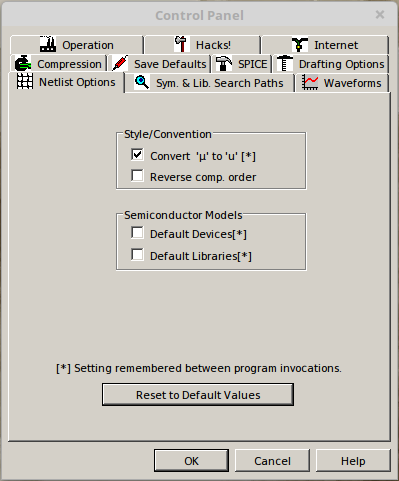
On this control panel select the Netlist Options tab and select the options as shown below:
Then select the
Sym. & Lib. Search Pathstab and enter the full path to ~/SLiCAP/ltspice. This directory contains all the SLiCAP symbol definitions (‘.asy’ files) for LTspice: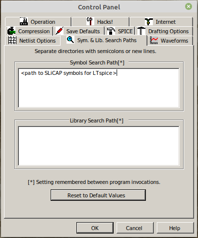
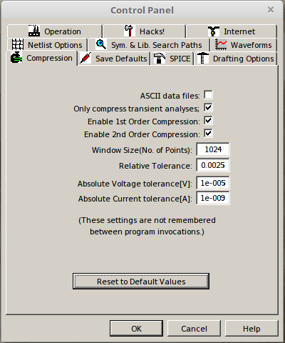
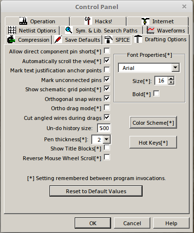
Then select the Drafting Options tab and change the font size and deselect the “Bold” checkbox as shown below. If you want, you can also select different colors for your schematics.
More information about schematic capture with LTspice
gSchem
The open source gSchem package can also be used in conjunction with SLiCAP. The use of gSchem as front-end for SLiCAP has been tested under Linux and Windows. However, for Linux please use Lepton-EDA instead.
An MSWindows installer for gSchem can be downloaded from: gEDA-20130122.zip. Netlist generation requires the gnet-spice-noqsi spice netlister. SLiCAP has built-in netlist generation with gSchem and this netlister.
MSWindows installation of gSchem is straightforward: simply extract the downloaded gEDA-20130122.zip archive and run the installer. In the drop down menu of the “Select Components” dialog box select “Program only”, for the rest accept default settings.
The netlister is installed by copying ‘gnet-spice-noqsi.scm’ from the downloaded and extracted archive to: C:\Program Files (x86)\gEDA\gEDA\share\gEDA\scheme\gnet-spice-noqsi.
You also need to create or modify the file ‘gafrc’ in the ~\.gEDA\ directory. It should have the following content:
(reset-component-library)
(component-library "C:/Program Files (x86)/gEDA/gEDA/share/gEDA/sym/slicap")
Important
SLiCAP schematics created with gSchem, should only comprise symbols from the SLiCAP gSchem symbol library:
>>> import SLiCAP as sl
>>> sl.ini.ini.gnetlist_syms
'/home/USER/USER/lib/python3.12/site-packages/SLiCAP/files/gSchem/'
Create a folder C:\Program Files (x86)\gEDA\gEDA\share\gEDA\sym\slicap and copy the contents of the above the gSchem symbol library to this folder.
If you wish to have a light background you can create or modify the file gschemrc in the ~\.gEDA\ directory. Its contents must be:
(load (build-path geda-rc-path "gschem-colormap-lightbg")) ; light background
Be sure you save these two files gafrc and gschemrc without any file extension.
For more information see: schematic capture with gSchem
Lepton-EDA
Lepton-EDA is a fork of geda-gaf. Please visit https://github.com/lepton-eda/lepton-eda for more information.
For an overview of SLiCAP symbols for Lepton-EDA, please view the above gSchem section.
Important
SLiCAP schematics created with Lepton-EDA, should only comprise symbols from the SLiCAP lepton-eda symbol library:
>>> import SLiCAP as sl
>>> ini.lepton_eda_syms
'/home/USR/ENV/lib/python3.12/site-packages/SLiCAP/files/lepton-eda/'.
This library must be added to lepton-eda.
Create or modify the file: ~/.config/lepton-eda/gafrc with the contents:
(reset-component-library)
(component-library "<path to SLiCAP symbol Library>" "SLiCAP")
If you wish to have a light background, you can create or modify the file ~/.config/lepton-eda/gschemrc in your home directory with the contents:
(load (build-path geda-rc-path "gschem-colormap-lightbg")) ; light background
Be sure you save these two files gafrc and gschemrc without any file extension.
SLiCAP uses the gnet-spice-noqsi spice netlister. It is included in the latest version of lepton-eda.
For compact node names (important for use in symbolic expressions) you need to reconfigure the default net name prefix.
This is how it should be done under Linux:
sudo lepton-cli config --system "netlist" "default-net-name" ""
For more information see: schematic capture with Lepton-EDA
Reserved component names
Below some restrictions for the reference designators of current sources in combination with specific analysis modes.
noise analysis: doNoise()
SLiCAP adds noise current sources in parallel with resistors that have a nonzero positive noise temperature. These current sources obtain the reference designator I_noise_<resID>, where resID is the reference designator of the resistor. After the noise analysis, these sources are removed from the circuit.
noise analysis
After noise analysis doNoise(), all independent current sources with reference designators starting with I_noise_ will be removed from the circuit.
dcvar analysis: doDCvar()
SLiCAP adds dc error current sources in parallel with resistors that have a nonzero dcvar value. These current sources obtain the reference designator I_dcvar_<resID>, where resID is the reference designator of the resistor. After the dcvar analysis, these sources are removed from the circuit.
dcvar analysis
After dcvar analysis doDCvar(), all independent current sources with reference designators starting with I_dcvar_ will be removed from the circuit.
time analysis: doTime()
In future versions, SLiCAP will add current sources with the Laplace transform of the initial conditions in parallel with capacitors and inductors taht have nonzero initial conditions. These current sources obtain the reference designator I_init_<elID>, where elID is the reference designator of the capacitor or inductor.
time analysis
In future versions, after time analysis doTime(), all independent current sources with reference designators starting with I_init_ will be removed from the circuit.
balanced circuits
SLiCAP can decompose balanced circuits into (unbalanced) differential-mode and common-mode equivalent circuits. This decomposition is based upon pairing of nodes and branches. Paired nodes and branches receive new names with extensions _C and _D for common-mode and differential-mode equivalent networks, respectively.
balanced circuits
The use of the extensions _C and _D in node names and device names in combination with the instruction argument convtype!=None should be avoided. This conflicts with the built-in decomposition method. For more information see: Work with Balanced circuits.
SLiCAP built-in parameters and Sympy reserved symbols =====================================================.
SLiCAP reserved variables
SLiCAP reserved variables are the frequency variable and the Laplace variable.
>>> import SLiCAP as sl
>>> sl.ini.frequency
f
>>> sl.ini.laplace
s
Important
Conflicts between function names in different packages can be prevented from by importing each package in its own namespace:
>>> import SLiCAP as sl
>>> import sympy as sp
>>> import numpy as np
SLiCAP global parameters
Global Parameters
Global parameters are defined in the file SLiCAPmodels.lib in the folder given by ini.main_lib_path. If global parameters are found in circuit element expressions or in circuit parameter definitions, SLiCAP automatically adds their global definition to the circuit parameter definitions.
 1"SLiCAPmodels"
 2
 3* Physical constants
 4********************
 5
 6.param
 7+ q             = 1.60217662e-19    ; Electron charge in [C]
 8+ c             = 2.99792458e+08    ; Speed of light in [m/s]
 9+ mu_0          = {4*pi*1e-7}       ; Permeability of vacuum in [H/m]
10+ epsilon_SiO2  = 3.9               ; Relative permittivity of SiO2 [-]
11+ k             = 1.38064852e-23    ; Boltzmann constant in [J/K]
12+ epsilon_0     = {1/mu_0/c^2}      ; permittivity of vacuum in [F/m]
13
14* Temperature and thermal voltage
15*********************************
16
17.param
18+ T             = 300               ; Default value of the absolute temperature in [K]
19+ U_T           = {k*T/q}           ; Thermal voltage [V]
CMOS18 EKV model parameters
Built-in CMOS18 EKV model parameter definitions are included in SLiCAP.lib in the folder given by ini.main_lib_path.
 1* Semiconductor subcircuit models EKV
 2*************************************
 3
 4* CMOS18 technology parameters for EKV models (SI units)
 5* DEFAULT EQUATIONS AND PARAMETERS taken from Binkley:
 6* "Tradeoffs and Optimization in Analog CMOS Design"
 7* Table 3.2
 8* Overlap capacitances set to typical values
 9* Early voltage per unit of length set to typical value
10********************************************************
11
12.param
13+ TOX_N18        = 4.1n    ; oxide thickness [m]
14+ Vth_N18        = 0.42    ; threshold voltage [V]
15+ N_s_N18        = 1.35    ; substrate factor [-]
16+ Theta_N18      = 0.28    ; vertical field mobility reduction coefficient [1/V]
17+ E_CRIT_N18     = 5.6M    ; lateral field strength for velocity saturation [V/m]
18+ u_0_N18        = 42.2m   ; zero field carrier mobility [m^2/V/s]
19+ CGBO_N18       = 1p      ; gate-bulk overlap capacitance [F/m]
20+ CGSO_N18       = 300p    ; gate-source and gate-drain overlap capacitance [F/m]
21+ CJB0_N18       = 1m      ; source/bulk drain/bulk capacitance [F/m^2]
22+ LDS_N18        = 180n    ; length of drain and source [m]
23+ KF_N18         = 3.2e-27 ; flicker noise (1/f noise) coefficient, zero for f_ell=0 [C/m^2]
24+ AF_N18         = 0.85    ; flicker noise exponent [-]
25+ V_KF_N18       = 1       ; flicker noise voltage dependency factor [V]
26+ VAL_N18        = 20M     ; Early voltage per unit of length [V/m]
27+ DVTDIBL_N18    = -0.008  ; dVth/dVDS
28+ DVTIDBLEXP_N18 = 3       ; exponent of dVth/dVDS
29+ beta_N18       = 0.8     ; Short channel effect exponent
30+ L_min_N18      = 180n    ; minimum channel length
31+ C_OX_N18       = {epsilon_0 * epsilon_SiO2 / TOX_N18}; oxide capacitance per unit of area [F/m^2]
32+ I_0_N18        = {2*N_s_N18*u_0_N18*C_OX_N18*U_T^2}  ; technology current [A]
33
34.param
35+ TOX_P18        = 4.1n    ; oxide thickness [m]
36+ Vth_P18        = -0.42   ; threshold voltage [V]
37+ N_s_P18        = 1.35    ; substrate factor [-]
38+ Theta_P18      = 0.35    ; vertical field mobility reduction factor [1/V]
39+ E_CRIT_P18     = 14M     ; lateral field strength for velocity saturation [V/m]
40+ u_0_P18        = 8.92m   ; zero field carrier mobility [m^2/V/s]
41+ CGBO_P18       = 1p      ; gate-bulk overlap capacitance [F/m]
42+ CGSO_P18       = 300p    ; gate-source and gate-drain overlap capacitance [F/m]
43+ CJB0_P18       = 1m      ; source/bulk drain/bulk capacitance [F/m^2]
44+ LDS_P18        = 180n    ; length of drain and source [m]
45+ KF_P18         = 2.4e-27 ; flicker noise (1/f noise) coefficient, zero for f_ell=0 [C^2/m^2]
46+ AF_P18         = 1.05    ; flicker noise exponent [-]
47+ V_KF_P18       = 0.25    ; flicker noise voltage dependency factor [V]
48+ VAL_P18        = 20M     ; Early voltage per unit of length [V/m]
Display schematics on html pages and in LaTeX reports
Scalable Vector Graphics .svg images are preferred for displaying on HTML pages, while Portable Document Format .pdf is preferred for LaTeX reports.
With KiCAD or Lepton-EDA running under Linux or MacOS, drawing-size
svgandpdfimages are generated with makeCircuit(). These image files will be placed in theimg/folder in the project directory.With KiCAD running under Windows, drawing-size
svgimages are generated with makeCircuit().With LTspice you can print schematics to a
pdffile using a PDF printer. Printing and rescaling cannot be invoked by SLiCAP.With gSchem running under MSwindows you can write your schematic file to a
pdffile. Printing and rescaling cannot be invoked by SLiCAP.
Converting and scaling pdf images
When running under MSWindows, you can use pdf2svg-1 or pdf2svg-2 for PDF to SVG conversion.
Alternatively, on all platforms, you can use Inkscape for this purpose. If you import pdf files with Inkscape use the import settings Poppler/Cairo import. With this selection, fonts are converted to Bezier curves.
Inkscape can also be used to resize images from page size to drawing size. This is required for correct display on HTML pages (svg or png format) or in LaTeX documents (pdf format). With KiCAD, SLiCAP uses built-in scripts. Lepton-EDA has such capabilities by default.
With gschem running under Linux or Mac OS you can write your schematic file to a eps file. These files can be converted into pdf files using the epstopdf command.
Ghostscript is an alternative often available in the package manager of Linux distributions. Otherwise Ghostscript versions can be downloaded from: Ghostscript.
Schematic file locations
A convenient way of working is to save your schematic circuit files in subfolders in the project folder.
If you create a KiCAD project in the SLiCAP project directory, the KiCAD schematic (file extension kicad_sch) is by default placed in the KiCAD project subfolder in the SLiCAP project directory.
Below a project directory structure according to this principle.
+ project folder
| - SLiCAP.ini
| - myProject.py
+-+ kicad
| + kicad_circuit_1
| | - kicad_circuit_1.kicad_sch
| | - ...
| + kicad_circuit_2
|   - kicad_circuit_2.kicad_sch
|   - ...
+-- ltspice
|   - ltspice_circuit_1.asc
|   - ltspice_circuit_2.asc
+-- lepton-eda
|   - lepton-eda_circuit_1.sch
|   - lepton-eda_circuit_2.sch
+-- gschem
|   - gschem_circuit_1.sch
|   - gschem_circuit_2.sch
+-- cir
|   - kicad_circuit_1.cir      <-- created with: sl.makeCircuit("kicad/kicad_circuit_1/kicad_circuit_1.kicad_sch")
|   - kicad_circuit_2.cir      <-- created with: sl.makeCircuit("kicad/kicad_circuit_2/kicad_circuit_2.kicad_sch")
|   - ltspice_circuit_1.cir    <-- created with: sl.makeCircuit("ltspice/ltspice_circuit_1.asc")
|   - ltspice_circuit_2.cir    <-- created with: sl.makeCircuit("ltspice/ltspice_circuit_2.asc")
|   - lepton-eda_circuit_1.cir <-- created with: sl.makeCircuit("lepton-eda/lepton-eda_circuit_1.sch")
|   - lepton-eda_circuit_2.cir <-- created with: sl.makeCircuit("lepton-eda/lepton-eda_circuit_2.sch")
|   - gschem_circuit_1.cir     <-- created with: sl.makeCircuit("gschem/gschem_circuit_1.sch")
|   - gschem_circuit_2.cir     <-- created with: sl.makeCircuit("gschem/gschem_circuit_2.sch")
+-- lib
+-- img
    - kicad_circuit_1.svg      <-- created with: sl.makeCircuit("kicad/kicad_circuit_1/kicad_circuit_1.kicad_sch")
    - kicad_circuit_1.pdf      <-- created with: sl.makeCircuit("kicad/kicad_circuit_1/kicad_circuit_1.kicad_sch")
    - kicad_circuit_2.svg      <-- created with: sl.makeCircuit("kicad/kicad_circuit_2/kicad_circuit_2.kicad_sch")
    - kicad_circuit_2.pdf      <-- created with: sl.makeCircuit("kicad/kicad_circuit_2/kicad_circuit_2.kicad_sch")
    - lepton-eda_circuit_1.svg <-- created with: sl.makeCircuit("lepton-eda/lepton-eda_circuit_1.sch")
    - lepton-eda_circuit_1.pdf <-- created with: sl.makeCircuit("lepton-eda/lepton-eda_circuit_1.sch")
    - lepton-eda_circuit_2.svg <-- created with: sl.makeCircuit("lepton-eda/lepton-eda_circuit_2.sch")
    - lepton-eda_circuit_2.pdf <-- created with: sl.makeCircuit("lepton-eda/lepton-eda_circuit_2.sch")
Netlist files (.cir extension) and image files (.svg and .pdf extensions) shown above, are created with makeCircuit() and by default placed in the cir folder and the img folder of the project directory, respectively.
Below an example of creating a circuit object from a KiCAD schematic file. The project folder is /USR/myProject/.
>>> import SLiCAP as sl
>>> sl.initProject("my project")
>>> cir = sl.makeCircuit("kicad/kicad_circuit_1/kicad_circuit_1.kicad_sch")

Compiling library: SLiCAP.lib.
Compiling library: SLiCAPmodels.lib.
Creating netlist of kicad//kicad_circuit_1/kicad_circuit_1.kicad_sch using KiCAD
Creating drawing-size SVG and PDF images of kicad/kicad_circuit_1/kicad_circuit_1.kicad_sch
Plotted to '/USR/myProject/img/kicad_circuit_1.svg'.
Done.
Obtain circuit elements information
Information about the circuit elements is available in the .elements attribute of the circuit object:
15# Display information about the expanded netlist elements
16for element in cir.elements.keys():
17    print("\n==============================================")
18    print("refDes    :", cir.elements[element].refDes)
19    print("nodes     :" , cir.elements[element].nodes)
20    print("refs      :" , cir.elements[element].refs)
21    print("model     :" , cir.elements[element].model)
22    if len(cir.elements[element].params.keys()):
23        print("\nModel parameters:")
24        for param in cir.elements[element].params.keys():
25            print(param, "=", cir.elements[element].params[param])
This yields:
==============================================
refDes    : C1
nodes     : ['out', '0']
refs      : []
model     : C

Model parameters:
value = C_s
vinit = 0

==============================================
refDes    : I1
nodes     : ['0', 'out']
refs      : []
model     : I

Model parameters:
value = 0
noise = 2*I_D*q
dc = -I_D
dcvar = sigma_ID**2

==============================================
refDes    : N1
nodes     : ['out', '0', 'out', '0']
refs      : []
model     : N

==============================================
refDes    : R1
nodes     : ['out', 'out']
refs      : []
model     : R

Model parameters:
value = R_t
noisetemp = T
noiseflow = 0
dcvar = sigma_R**2
dcvarlot = 0
For more information about the SLiCAP circuit object, see the: circuit class definition
For more information about schematic capture (built-in symbols, models and subcircuits), see Schematic capture for SLiCAP
Display circuit data on HTML pages and in LaTeX documents
The report module Create reports, discusses how HTML snippets and LaTeX snippets can be created for variables, expressions, equations and tables.